Types of flowmeters
Flow and flowmetry can be divided into two groups: flow measurement or flow in open channel and closed pipe flow .
Open channel flowmeters, as the name implies, are used to measure the flow of channels and paths that have a free or uncovered surface and are open to the atmosphere. Currents in canals or outlet pipelines such as drains and sewers that are in the canal or path that are not full.
In open channels, the force of gravity causes the current to pass through and moves downward as the water constantly falls or decreases in height.
The flow flows in a closed channel or pipe when there is a pressure difference in the pipe. Flow in water supply pipes or central heating pipes are typical examples. The flow mainly depends on the pressure difference between the ends, the distance between the ends, the channel area and the hydraulic properties of the barrier pipe and limitations such as bending and pipe shape.
Principles of flow and flow measurements in fluids
- • Flowmetry through pressure difference
• Flowmeter based on fluid velocity
• Positive displacement
flowmeter • Mass or copper flowmeter Flowmeter
• Flowmeter for open channel - ponds, flume, river, etc.
Flowmeter with pressure difference mechanism
In a flowmeter with a pressure difference mechanism based on the physical laws of fluids or Bernoulli's law in this equation or principle in fluid mechanics explains the behavior of fluid flow in uniform cases and the mathematical form is the law of conservation of energy in fluids. Simply put, in a flowing stream, an increase in flow velocity coincides with a decrease in pressure, provided that the height of the fluid remains constant. The Bernoulli equation is a more precise expression of this principle, in other words, if the velocity of a fluid increases, the pressure it exerts on a surface decreases, and vice versa.
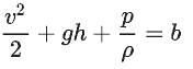
In the above equation
v Fluid velocity
g Acceleration of the earth
h The height from the desired point in the direction of the earth's gravity
p Pressure in the fluid
ρ is the density of the fluid.
In short, the formula is dp = ρ v2 / 2 , which shows that the pressure difference is directly related to the velocity square by obtaining the velocity and having the flow cross section above the desired cross section.
The most common flowmetry models using pressure differences are as follows.
Orifice Plates Orifice Plates
• Flow Nozzles Nozzles
• Venturi Tubes Venturi Tubes
• Variable Area - Rotameters Rotameters or variable levels
Orpheus Plate
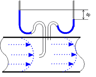
By creating an obstacle in the path with the help of a perforated metal plate, a pressure difference is created in the upstream and downstream side of the flow path in the pipe, which according to Bernoulli's law is proportional to the square of fluid velocity and is based on flowmetric mechanism
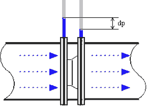
The mechanism of Orphis plates is simple and cheap and can be offered for almost any application and any material. The sharpness of their lips varies to reduce measurement problems.
Venturi Flowmeter
Due to its simplicity and good reliability, the Venturi flowmeter is often used in applications where a higher to lower ratio or lower pressure drop than the Orphis Plate is required.
In a Venturi tube, the flow of liquids is measured by reducing the flow rate of the flow section in the path that causes the pressure difference. The fluid exits after the confined or narrowed area through the outlet, which causes the pressure to return to the previous state up to about 80% of the differential pressure produced in the confined area.
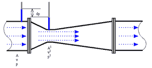
With proper tubing and flow calibration, the Venturi Tube can measure with full accuracy about 10% of its full scale range with full accuracy, while with a range ratio of 10: 1 to a wider range than the Orphis Plate. cover. Note that the barometer for the Venturi model must be installed under a pipe or hydraulic line.
Nozzle
Nozzle flowmetry is often used to measure air and gas flow in industrial applications.
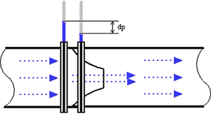
The flow nozzle is relatively simple and inexpensive and is made of materials for many applications. The ratio of suffering and accuracy can be compared to Orphis Plate.
Sonic nozzle or critical point (choked)
When a gas is accelerated through a nozzle, the speed increases and the pressure and density of the gas decrease. The maximum speed is achieved in the nozzle throat or the minimum area where the speed of a Mach or Sonic is achieved. At this stage, it is not possible to increase the current by reducing the downstream pressure and the current or flow is choked.
This condition is used in many control systems to maintain a constant, accurate and reproducible flow without the effect of downstream pressure.
Recovery of pressure drop in Orphis Plate, Nozzle and Venturi flowmeters
After creating a pressure difference in the differential flowmeters, the fluid passing through the outlet or pressure recovery section, where the differential pressure generated in the confined area is somewhat improved. The following diagram shows the difference in this recovery.
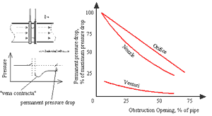
As you can see, the pressure drop in the Orphis Plate is significantly greater than in the Venturi flowmeter .
Variable surface rotameter or flowmeter
Rotameter A rotameter consists of a vertical glass (or plastic) tube with a larger end at the top of the plate and a calibrated float that moves freely up and down inside the tube. Fluid flow and buoyancy cause the force exerted on the float to overcome the force due to its weight and reach the dynamic equilibrium state along the tube along with increasing pressure and differential pressure changes, and reach a calibrated state in proportion to the flow rate that Prove the calibrated vertical face.
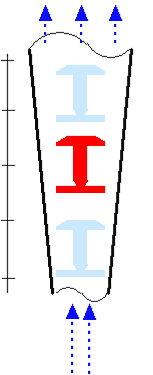
Rotameter with a range of 10 has the ability to adjust the range and calibration and with an accuracy between 10 to one percent full scale has the ability to measure the flow of liquids and gases. In more advanced models, a float or magnetic float allows the device to receive a switch or signal output.
Flowmetry with speed measurement
In a flowmeter, the flow velocity is calculated by measuring the velocity at one or more points in the flow, and the total flow from the integral of these velocities is calculated at the point where the flow is displaced.
Pitot Tubes Pitot Tubes
Pitot tube method Pitot tube is one of the most common (and cheapest) methods for measuring fluid flow, especially in air applications such as ventilation and air conditioning systems, even used in aircraft to measure speed.
The pitot tube measures the flow rate of the fluid resulting from the conversion of the kinetic energy of the flow into potential energy. The use of a pitot tube is limited to measuring a point.
Dynamic pressure can be measured in the velocity profile using the "annubar" probe or the Pitot multi-point probe. Annubar performs a speed average.
Flowmeter by calorimeter
The calorimetric principle for measuring fluid flow is based on two temperature sensors in close contact with the liquid while being thermally insulated from each other.
One of the two sensors is continuously heated and the fluid cooling effect is used to monitor the flow rate. In a constant (no flow) liquid state, there is a constant temperature difference between the sensor with the temperature element and the temperature sensor. As the fluid flow increases, heat energy is drawn from the heat sensor and the temperature difference between the sensors decreases. Its reduction is proportional to the velocity of the fluid flow.
The thermal conductivity of the liquid causes the response time to be different. In general, lower thermal conductivity requires more speed for proper measurement.
Calorimetric flowmeter flow can have relatively high accuracy in low flow currents.
Turbine flowmeter
Turbine flowmeters come in a wide variety of designs from different companies, but in general they all work on the simple principle that if a fluid moving through a tube puts pressure on the edges of the operating turbine, the turbine will start to spin. he does. Rotation speed is measured to calculate the flow. The range ratio of turbine flowmeters may be more than 100: 1, and in certain conditions the accuracy may be better than +/- 0.1% if it is calibrated for a single fluid and the conditions of use are constant.
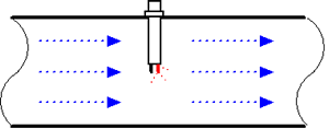
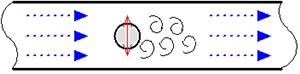
Vertex flowmeter
If an obstruction or obstruction occurs in the fluid flow, it causes a vortex in the downstream flow, and each obstruction has a specific flow velocity to create a vortex. In fact, vortices in fluid are an example of the creation of low-pressure areas downstream that are created by an obstacle. This mechanism is the basis of the work of vortex flowmeters. In practice, by installing sensors in the place where these vortices are most generated and measuring their intensity, the amount of flow can be measured.
Electromagnetic flowmeter
An electromagnetic flowmeter operates according to Faraday's law in electromagnetic induction, which states that a voltage is generated during the movement of a conductor through a magnetic field. The liquid acts as a conductor, and the magnetic field generates a mild voltage by coils outside the tube and an electric current passing through them.
The voltage generated is directly proportional to the current flow. The two electrodes mounted on the wall of the tube detect the voltage measured by a secondary element.
The electromagnetic flowmeter can measure hard and corrosive liquids depending on the type of electrodes in contact with the fluid, and it is possible to measure the current in both directions with equal accuracy.
Electricity consumption in electromagnetic flowmeters is relatively high and can only be used for liquids such as water with electrically conductive water.
Ultrasonic flowmeter
The effect of the motion of an audio source and its effects on the frequency of sound is observed and described by Johann Doppler. The effect of the motion of an audio source and its effects on the frequency of sound is observed and described by Johann Doppler.
The frequency of the reflected signal changes with changes in the velocity and direction of the fluid flow. If the fluid moves towards the converter, the frequency of the return signal increases, and similarly, if the fluid moves in the opposite direction of the converter, the frequency of the return signal decreases.
The frequency difference is equal to the reflected frequency minus the initial frequency and can be used to calculate the fluid flow velocity.
Positive displacement flowmeter
Positive Displacement Flowmeter Measures the flow of fluids in specific modulus with rotors fitted into its chamber. The specified fixed volumes are displaced between the rotors in the shaft section and by counting them, the amount of flow is accurately measured.
The number of rotations of the rotor is counted by an alternating electronic pulse transmitter and converted to the volume and flow of the fluid.
Positive displacement rotor construction can be done in several ways:
• Reciprocating pistons have single and multiple piston types.
Oval gears are designed in such a way that two oval gears with coordinated and closely spaced teeth are designed in such a way that a constant amount of liquid passes through the flowmeter in each rotation. The shaft rotation speed can be controlled to achieve a certain flow velocity.
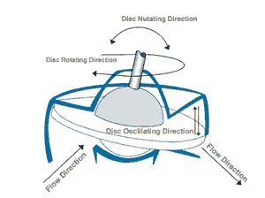
Nutating disks are removable disks mounted on a concentric sphere in a spherical chamber. The pressure of the liquid through the measuring chamber causes the disc to rotate in a rotating path without rotating on its own axis. This is the only moving part in the measuring chamber.
• Van rotary model flowmeters are designed from two or more equal rotating parts inside the chamber in which the impellers are in constant contact with the shell and the body of the equipment. A constant volume of liquid exits the flowmeter at each turn and in contact with the memory. The rotation of the impellers is counted and recorded in volumetric units.
Positive displacement flowmeters are used for all relatively non-measurable liquids such as heating oils, lubricating oils, polymer additives, animal and vegetable fats, printing inks, Dichlorodifluoromethane R-12 and many more.
Accuracy may be up to 0.1% of full with TurnDown 70: 1 or higher
Mass flowmeters
Mass flowmeters have the ability to directly measure the mass of material displaced in the tube. In chemical reactions, petrochemical industries, temperature transfer, mass flowmeters are commonly used, such as corialis or copper thermal
Thermal mass flowmeter
Thermal mass flowmeter has traditionally been used to measure gas, but in some models it is used to measure liquid flow. These mass flow meters operate independently of density, pressure and viscosity. Mass heat flowmeters use a heated and isolated sensor through the fluid flow path. Fluid flow causes heat transfer from the sensor part. The heat transferred is directly proportional to the mass flow rate. The sensors never come into direct contact with the liquid. The electronic part of the device includes a current analyzer, a temperature compensator and a signal modulator that provides linear output directly to the mass flow.
Corialis Flowmeter
Direct mass measurement of Corellis flowmeters is a unique technology compared to other methods. Mass measurement in this method is independent of changes in pressure, temperature, viscosity and sensitive density, and in this method with the possibility of measuring the flow of various liquids, gases, sludge, etc. are universal flowmeters.
The Coriolis Flowmeter uses the Coriolis effect to measure the amount of mass by means of a U-shaped moving component that vibrates and causes angular harmonic oscillation as the flow passes. Due to Coriolis forces, the tubes move and the additional vibration components oscillate. This additional component causes a phase change in some parts of the tube that can be measured with a sensor.
Corylol flowmeters are generally very accurate, better than +/- 0.1% with a range ratio of more than 100: 1. The Cryolis flowmeter can be used to measure condensed liquids.
Open channel flowmeters
"Open channel" refers to any channel in which the flowing fluid has a free surface. Includes tunnels, uncompressed sewage, pipes, canals, streams and rivers. Of the many techniques for monitoring open channel flows, depth-related methods are the most common. These techniques assume that the instantaneous flow rate may be determined by measuring the water depth or head and water height. Basins and foams are the oldest and most extensive main devices for measuring open channel currents.
Wier or seal on the principle act as a blockage in one channel, the water pulls back or head and upper level behind the barrier. This higher altitude is a function of the flow velocity, and therefore a function of the flow rate through the device. Weirs of rods consist of vertical plates with sharp protrusions. The top of the page can be straight or curved. Seals are classified according to the shape of the gap. The basic types are V-neck, rectangular and trapezoidal.
Flume or ducts are generally used when the loss of head and height should be minimal, or if the flowing liquid contains large amounts of suspended solids. Ducts are also used to measure open channel flow when venturi pipes are connected to closed pipes. Popular popular channels are Parshall and Palmer-Bowlus.